- Sign In
- |
- Sign Up
- |
- My Quote (0)
- |
- CART (0)
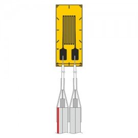
This pre-wired strain gauge has a 120 Ω grid measuring 0.012 x 0.077" (0.3 x 1.96 mm) on a polyimide carrier. It operates over 14 to 311°F (-10 to 155°C) with 3.3' (1 m) leads, 2 conductors. It suits experimental stress analysis and static strain measurement.
This pre-wired strain gauge has a 120 Ω grid measuring 0.012 x 0.077" (0.3 x 1.96 mm) on a polyimide carrier. It operates over 14 to 311°F (-10 to 155°C) with 3.3' (1 m) leads, 2 conductors. It suits experimental stress analysis and static strain measurement.
Linear pattern precision gauges with miniature and medium length grids are for general purpose and stress analysis applications. Available with either two 1-meter leads or three 3-meter leads and 120 or 350 Ω resistance. All models are compensated for steel.
Features
Applications
| Series | KFH Series |
| Type | pre-wired strain gauge |
| Gauge resistance | 120 Ω |
| Grid size | 0.012 x 0.077" (0.3 x 1.96 mm) |
| Temperature range | 14 to 311°F (-10 to 155°C) |
| Leads | 3.3' (1 m) leads, 2 conductors |
| Strain Gauge Construction | Foil strain gauge with embedded measuring grid |
| Measuring Grid Material | Constantan |
| Measuring Grid Thickness | 3.8 or 5 μm (150 or 197 microinch), depending upon strain gauge type |
| Carrier Material | Polyimide |
| Carrier Thickness | 45 ± 10 μm (1.772 ± 394 microinch) |
| Connections | PTFE wire, Ø 0.051 mm2, approximately 1.97" (50 mm) long, connected to AWG 28 ribbon cables (PVC insulated) through solder sleeves in 2- or 3-wire configurations |
| Nominal Resistance | 120 or 350 Ω depending upon gauge |
| Resistance Tolerance | ±0.35% |
| Gauge Factor | approximately 2 (stated on package) |
| Gauge Factor Tolerance | ±1% |
| Temperature Coefficient of Gauge Factor | (115 ± 10) x 10-6 1/K [(64 ± 5.5) x 10-6 1/°F] |
| Reference Temperature | 73°F (23°C) |
| Operating Temperature Range for Static Measurement | 14 to 311°F (-10 to 155°C) |
| Operating Temperature Range for Dynamic Measurement | 14 to 311°F (-10 to 155°C) |
| Fatigue Life | Achievable number of load cycles at alternating strain of ±1000 μm/m with zero point variation ≤ 300 μm/m: >1 x 10⁷ (test was stopped) |
| Strain Gage Construction | Foil strain gauge with embedded measuring grid |
| Gage Factor | approximately 2 (stated on package) |
| Gage Factor Tolerance | ±1%; with 0.02" (0.6 mm) and 0.06" (1.5 mm) grid length ±1.5% |
| Temperature Coefficient of Gage Factor | (115 ± 10) x 10-6 1/K [(64 ± 5.5) x 10-6 1/°F] |
| Nominal Value of Gage Factor Temperature Coefficient | Specified on each package |
| Operating Temperature Range (static measurement, zero point related), PTFE cable | 14 to 311°F (-10 to 155°C) |
| Operating Temperature Range (dynamic measurement, not zero point related), PTFE cable | 14 to 311°F (-10 to 155°C) |
| Transverse Sensitivity (linear 3 mm 120 Ω gage) | ±0.2% |
| Temperature Response | Specified on each package (matched to coefficient of thermal expansion; adapted via LY41, LY42, LY43 table) |
| Coefficient of Thermal Expansion α for aluminum | 23 x 10-6 1/K (12.8 x 10⁻⁶ 1/°F) |
| Coefficient of Thermal Expansion α for plastic material | 65 x 10-6 1/K (36.1 x 10⁻⁶ 1/°F) |
| Coefficient of Thermal Expansion α for austenitic steel | 16 x 10-6 1/K (8.9 x 10⁻⁶ 1/°F) |
| Coefficient of Thermal Expansion α for titanium | 9 x 10⁻⁶ 1/K (5.0 x 10⁻⁶ 1/°F) |
| Coefficient of Thermal Expansion α for molybdenum | 5.4 x 10⁻⁶ 1/K (3.0 x 10⁻⁶ 1/°F) |
| Coefficient of Thermal Expansion α for quartz | 0.05 x 10⁻⁶ 1/K (0.3 x 10⁻⁶ 1/°F) |
| Tolerance of Temperature Response | 14 to 248°F (-10 to 120°C) |
| Mechanical Hysteresis (reference temp, strain 1000 µm/m, linear 3 mm 120 Ω gage, adhesive SG496) | 1 μm/m at 1st load cycle; 0.5 μm/m at 3rd load cycle |
| Maximum Elongation (reference temp, linear 3 mm 120 Ω gage), positive direction | 20,000 ± 12% μm/m |
| Maximum Elongation (reference temp, linear 3 mm 120 Ω gage), negative direction | 25,000 ± 2.5% μm/m |
| Fatigue Life (linear 3 mm 120 Ω gage, alternating strain ±1000 µm/m), zero point variation ≤ 300 µm/m | > 1 x 10⁷ (test was stopped) |
| Fatigue Life, zero point variation ≤ 30 µm/m | 5 x 10⁶ |
| Minimum Radius of Curvature (longitudinal & transverse, reference temp) within measuring grid area | 0.012" (0.3 mm) |
| Minimum Radius of Curvature within solder tab area | 0.394" (10 mm) |
| Applicable Bonding Materials | Cold Cure Adhesives SG496, SG401; Heat Cure Adhesives TT300 |
| Grid Length Range | 0.02 to 0.79" (0.6 to 20 mm) |
| Termination | Two 3.28' (1 m) leads or three 9.84' (3 m) leads; 2- or 3-wire models |
| Temperature Compensation | ST (compensated for steel) |
| Maximum Permitted Bridge Energizing Voltage | Per model, 1.5 to 20 Vrms (e.g. 0.01" (0.3 mm) grid 120 Ω = 1.5 Vrms; 0.24" (6 mm) grid 350 Ω = 15 Vrms; XY/rosette patterns vary) |
Click on a category to view a selection of compatible accessories with the Omega KFH Series Pre-Wired Strain Gauge, 120 Ω, 0.012 x 0.077" grid, 3.3' leads, 2 conductors, 5-pack.

| Series | KFH Series |
| Type | pre-wired strain gauge |
| Gauge resistance | 120 Ω |
| Grid size | 0.012 x 0.077" (0.3 x 1.96 mm) |
| Temperature range | 14 to 311°F (-10 to 155°C) |
| Leads | 3.3' (1 m) leads, 2 conductors |
| Strain Gauge Construction | Foil strain gauge with embedded measuring grid |
| Measuring Grid Material | Constantan |
| Measuring Grid Thickness | 3.8 or 5 μm (150 or 197 microinch), depending upon strain gauge type |
| Carrier Material | Polyimide |
| Carrier Thickness | 45 ± 10 μm (1.772 ± 394 microinch) |
| Connections | PTFE wire, Ø 0.051 mm2, approximately 1.97" (50 mm) long, connected to AWG 28 ribbon cables (PVC insulated) through solder sleeves in 2- or 3-wire configurations |
| Nominal Resistance | 120 or 350 Ω depending upon gauge |
| Resistance Tolerance | ±0.35% |
| Gauge Factor | approximately 2 (stated on package) |
| Gauge Factor Tolerance | ±1% |
| Temperature Coefficient of Gauge Factor | (115 ± 10) x 10-6 1/K [(64 ± 5.5) x 10-6 1/°F] |
| Reference Temperature | 73°F (23°C) |
| Operating Temperature Range for Static Measurement | 14 to 311°F (-10 to 155°C) |
| Operating Temperature Range for Dynamic Measurement | 14 to 311°F (-10 to 155°C) |
| Fatigue Life | Achievable number of load cycles at alternating strain of ±1000 μm/m with zero point variation ≤ 300 μm/m: >1 x 10⁷ (test was stopped) |
| Strain Gage Construction | Foil strain gauge with embedded measuring grid |
| Gage Factor | approximately 2 (stated on package) |
| Gage Factor Tolerance | ±1%; with 0.02" (0.6 mm) and 0.06" (1.5 mm) grid length ±1.5% |
| Temperature Coefficient of Gage Factor | (115 ± 10) x 10-6 1/K [(64 ± 5.5) x 10-6 1/°F] |
| Nominal Value of Gage Factor Temperature Coefficient | Specified on each package |
| Operating Temperature Range (static measurement, zero point related), PTFE cable | 14 to 311°F (-10 to 155°C) |
| Operating Temperature Range (dynamic measurement, not zero point related), PTFE cable | 14 to 311°F (-10 to 155°C) |
| Transverse Sensitivity (linear 3 mm 120 Ω gage) | ±0.2% |
| Temperature Response | Specified on each package (matched to coefficient of thermal expansion; adapted via LY41, LY42, LY43 table) |
| Coefficient of Thermal Expansion α for aluminum | 23 x 10-6 1/K (12.8 x 10⁻⁶ 1/°F) |
| Coefficient of Thermal Expansion α for plastic material | 65 x 10-6 1/K (36.1 x 10⁻⁶ 1/°F) |
| Coefficient of Thermal Expansion α for austenitic steel | 16 x 10-6 1/K (8.9 x 10⁻⁶ 1/°F) |
| Coefficient of Thermal Expansion α for titanium | 9 x 10⁻⁶ 1/K (5.0 x 10⁻⁶ 1/°F) |
| Coefficient of Thermal Expansion α for molybdenum | 5.4 x 10⁻⁶ 1/K (3.0 x 10⁻⁶ 1/°F) |
| Coefficient of Thermal Expansion α for quartz | 0.05 x 10⁻⁶ 1/K (0.3 x 10⁻⁶ 1/°F) |
| Tolerance of Temperature Response | 14 to 248°F (-10 to 120°C) |
| Mechanical Hysteresis (reference temp, strain 1000 µm/m, linear 3 mm 120 Ω gage, adhesive SG496) | 1 μm/m at 1st load cycle; 0.5 μm/m at 3rd load cycle |
| Maximum Elongation (reference temp, linear 3 mm 120 Ω gage), positive direction | 20,000 ± 12% μm/m |
| Maximum Elongation (reference temp, linear 3 mm 120 Ω gage), negative direction | 25,000 ± 2.5% μm/m |
| Fatigue Life (linear 3 mm 120 Ω gage, alternating strain ±1000 µm/m), zero point variation ≤ 300 µm/m | > 1 x 10⁷ (test was stopped) |
| Fatigue Life, zero point variation ≤ 30 µm/m | 5 x 10⁶ |
| Minimum Radius of Curvature (longitudinal & transverse, reference temp) within measuring grid area | 0.012" (0.3 mm) |
| Minimum Radius of Curvature within solder tab area | 0.394" (10 mm) |
| Applicable Bonding Materials | Cold Cure Adhesives SG496, SG401; Heat Cure Adhesives TT300 |
| Grid Length Range | 0.02 to 0.79" (0.6 to 20 mm) |
| Termination | Two 3.28' (1 m) leads or three 9.84' (3 m) leads; 2- or 3-wire models |
| Temperature Compensation | ST (compensated for steel) |
| Maximum Permitted Bridge Energizing Voltage | Per model, 1.5 to 20 Vrms (e.g. 0.01" (0.3 mm) grid 120 Ω = 1.5 Vrms; 0.24" (6 mm) grid 350 Ω = 15 Vrms; XY/rosette patterns vary) |
Click on a category to view a selection of compatible accessories with the Omega KFH Series Pre-Wired Strain Gauge, 120 Ω, 0.012 x 0.077" grid, 3.3' leads, 2 conductors, 5-pack.